Demo & Examples
See it in action.
Real prompts, real output, real results. Everything below was generated by the MCP server.
Visual demos
Real screenshots & live video.
Captured from actual MCP sessions — topology diagrams, agent tool calls, and running router configs.
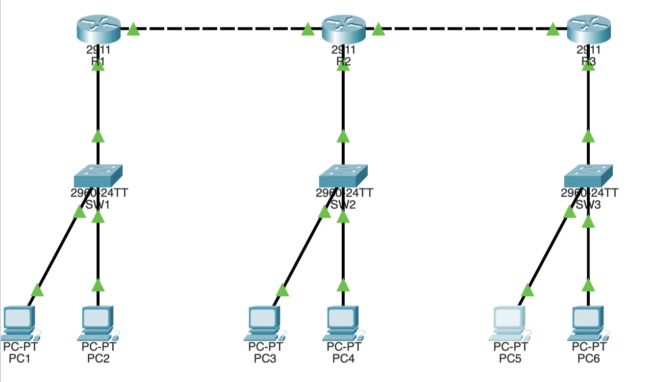
Topology in Packet Tracer
A deployed 3-router OSPF topology with DHCP pools — all created from a single natural language prompt.
Installing the MCP Control Center (V4)
One-time setup: add the project’s own .pts extension via Extensions → Scripting → Configure PT Script Modules, then open Extensions → MCP BUILDER — it auto-connects, no bootstrap.
Live Deploy in Action
Watch devices appear in Packet Tracer in real-time as the HTTP bridge streams commands to the MCP Control Center extension.
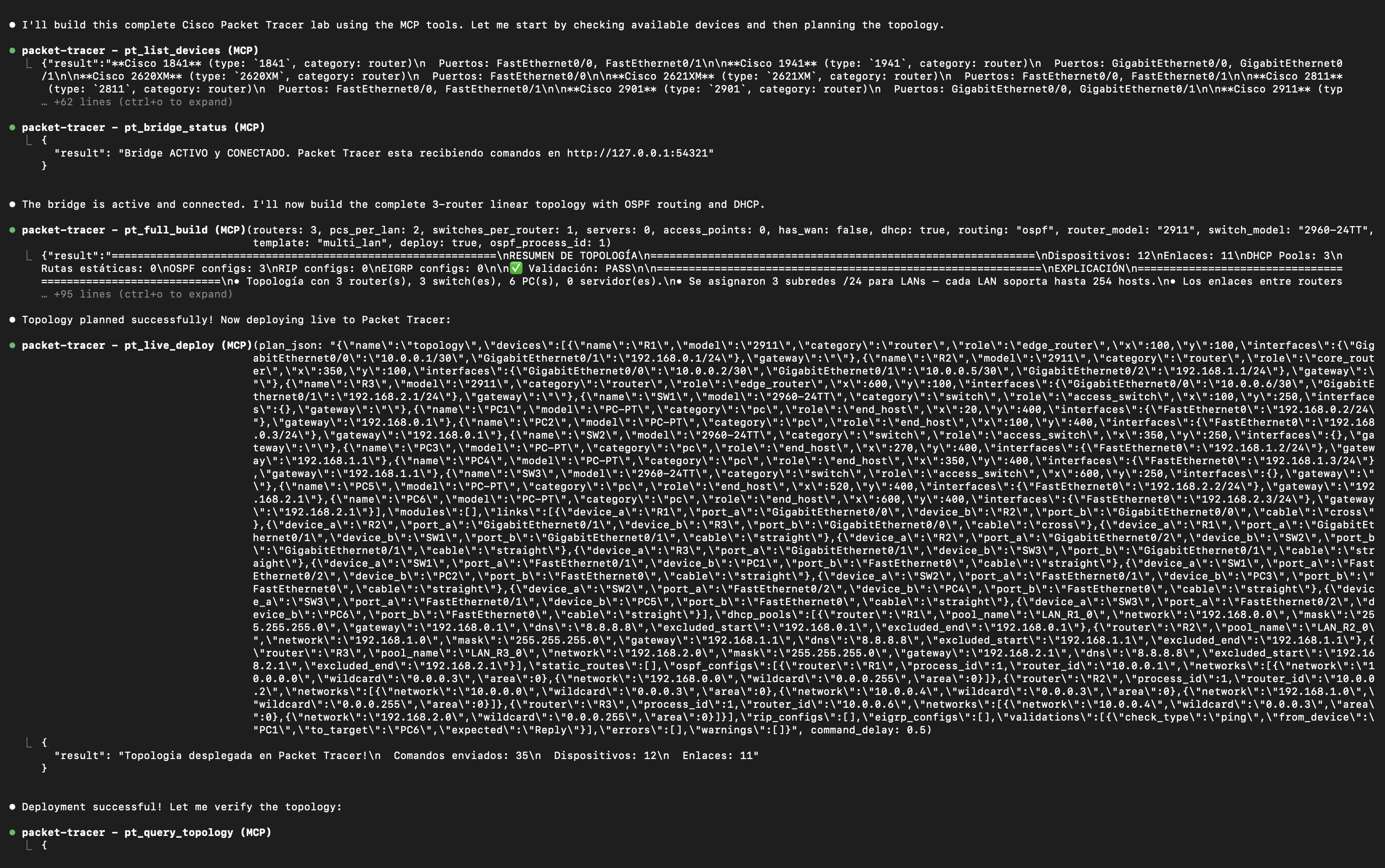
AI Agent Interaction
See how an AI agent (VS Code Copilot or Claude) uses MCP tools step by step to build a topology.
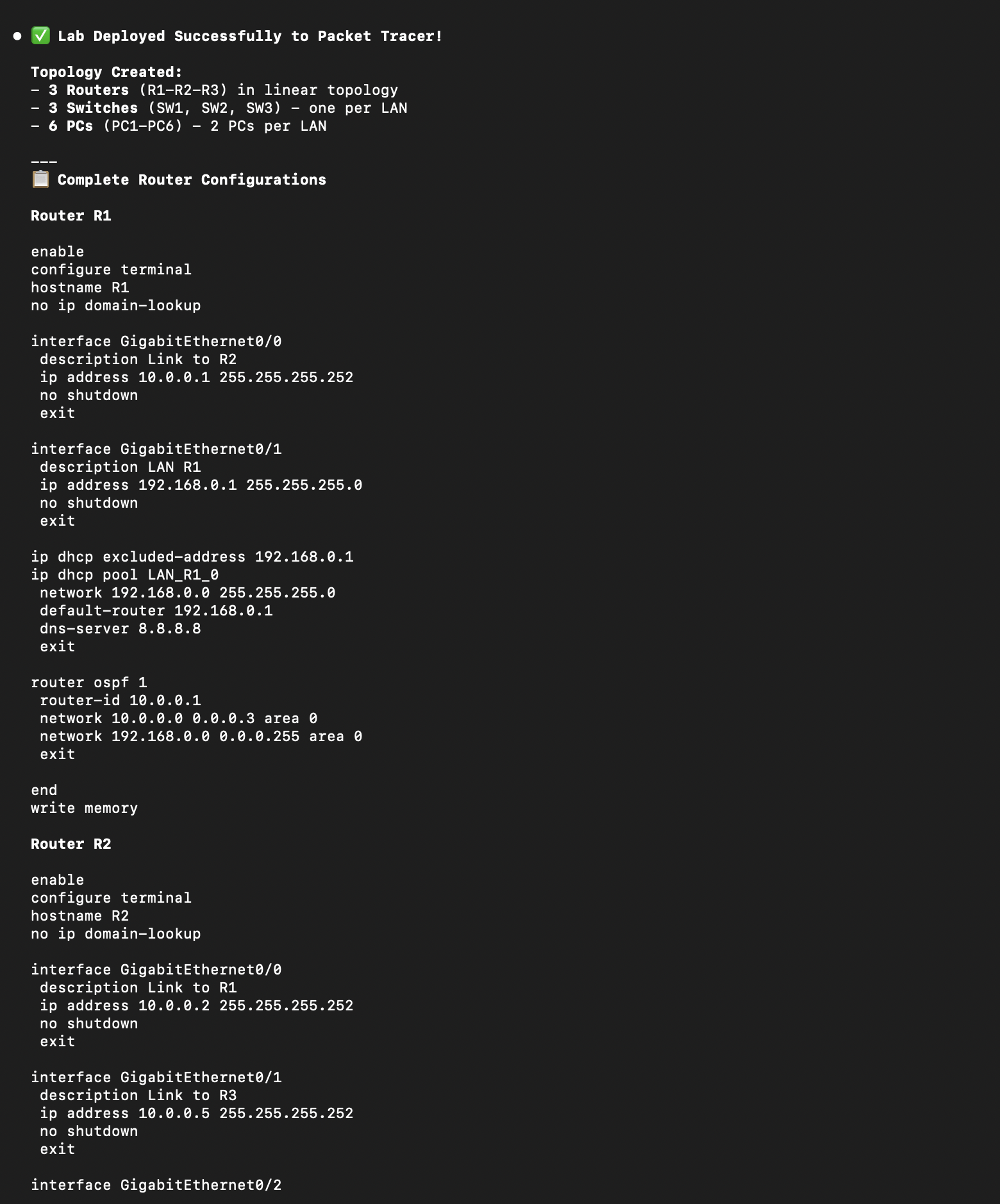
CLI Configs Applied
Router running-config showing OSPF, DHCP, and interface configurations — all auto-generated.
Example prompts
Copy a prompt and try it yourself.
Simple 2-Router Lab
"Build a 2-router lab with static routing and 2 PCs per LAN"
Two routers connected via WAN. Each with its own LAN. Great for beginners learning subnetting.
OSPF Lab with DHCP
"Create a 3-router OSPF lab with DHCP enabled"
Three routers running OSPF area 0 with DHCP on every LAN. A realistic branch-office topology.
Single LAN
"I just need 1 router, 1 switch, and 4 PCs"
The simplest topology for testing basic IP addressing and connectivity.
One-Shot Full Build
"Full build: 3 routers, OSPF, DHCP, WAN, 2 PCs per LAN"
Uses pt_full_build — plan, validate, auto-fix, generate script + configs + explanation, all in one call.
Triangle Redundancy
"3 routers in a triangle with redundant links and OSPF"
Three routers fully meshed for redundancy. OSPF handles convergence automatically.
Hub and Spoke WAN
"Hub-spoke topology: 1 central router, 4 branches, EIGRP"
Classic enterprise design. Central HQ router connected to branch offices with WAN links.
What you get
Real output from the server.
Three files generated for every topology — a topology build script (JS), router configs, and a plain-English explanation.
The build script runs through the project’s own MCP Control Center extension. Its script-engine logic was inspired by PTBuilder, but they are separate, independent projects — you install our extension, not PTBuilder.
Topology Build Script
topology.js // Auto-generated by MCP Packet Tracer
addDevice("R1", "2911", 200, 150);
addDevice("R2", "2911", 500, 150);
addDevice("SW1", "2960-24TT", 200, 300);
addDevice("SW2", "2960-24TT", 500, 300);
addLink("R1", "GigabitEthernet0/0",
"SW1", "GigabitEthernet0/1", "straight");
addLink("R1", "GigabitEthernet0/1",
"R2", "GigabitEthernet0/1", "cross");
addDevice("PC1", "PC-PT", 100, 450);
addDevice("PC2", "PC-PT", 300, 450); Router CLI Config
R1_config.txt enable configure terminal hostname R1 interface GigabitEthernet0/0 ip address 192.168.1.1 255.255.255.0 no shutdown ip dhcp pool LAN_R1 network 192.168.1.0 255.255.255.0 default-router 192.168.1.1 dns-server 8.8.8.8 router ospf 1 network 192.168.1.0 0.0.0.255 area 0 network 10.0.0.0 0.0.0.3 area 0 end write memory
Natural Language Explanation
explanation.md Topology: 2 routers, 2 LANs, 1 WAN link • R1 (2911) at position (200, 150) - Gig0/0 → SW1 — LAN gateway 192.168.1.1/24 - Gig0/1 → R2 — WAN 10.0.0.1/30 • R2 (2911) at position (500, 150) - Gig0/0 → SW2 — LAN gateway 192.168.2.1/24 - Gig0/1 → R1 — WAN 10.0.0.2/30 DHCP enabled on both LANs. OSPF area 0 on all router interfaces.
Want to try it yourself?
Install the server, connect your MCP client, and use any of these prompts.